8Bit/16Bit Parallel TFT Library for WiringPi
This is library for RaspberryPi.
You can use a TFT Shield for UNO R3.
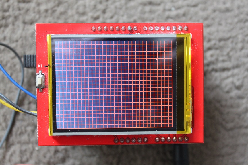
This library can show a chart to TFT Shield.

Primarily, these TFT Shiled is the one for Arduino.
This may works with other boards like OrangePi/NanoPi.
Supported TFT controllers:
Generic 8bit Sheild
- ILI9320(240x320)
- ILI9325(240x320)
- ILI9341(240x320)
- ILI9342(240x320)
- ILI9481(320x480)
- ILI9486(320x480)
- ILI9488(320x480)
- SPFD5408(240x320 Same as ILI9320)
- R61505U(240x320 Same as ILI9320)
- R61509V(240x400)
- ST7781(240x320)
- ST7783(240x320 Same as ST7781)
- ST7793(240x400 Same as R61509)
- ST7796(320x480 Same as ILI9486)
Generic 16bit Sheild
OPEN-SMART Products
- OPEN-SMART ILI9225 TFT-Shield(176x220)
- OPEN-SMART ILI9327 TFT-Shield(240x400)
- OPEN-SMART ILI9340 TFT-Shield(240x320)
- OPEN-SMART S6D1121 16Pin-Parallel(240x320)
- OPEN-SMART ST7775 16Pin-Parallel(176x220 Same as ILI9225)
- OPEN-SMART ST7783 16Pin-Parallel(240x320)
- OPEN-SMART R61509V 16Pin-Parallel(240x400)
- OPEN-SMART ILI9488 16Pin-Parallel(320x400 Color inversion)
These are all 2.4 inch, 320x240 TFTs.

3.95 inches is almost twice as large as 2.4 inches.

These are OPEN-SMART 16Pin-Parallel Products.

Software requirement
- WiringPi Library
This project uses the wiringPiSetup() function to initialize GPIOs.
If you use it on a board other than the RPI board, you may need to change the GPIO number.
As far as I know, there are these libraries.
- WiringPi for OrangePi
- WiringPi for OrangePi Zero
- WiringPi for OrangePi3
- WiringPi for BananaPi
- WiringPi for NanoPi
- WiringPi for Pine-64
Wirering for 8Bit Parallel
| TFT |
|
RPI |
| LCD_RST |
– |
Pin#7 |
| LCD_CS |
– |
Pin#3 |
| LCD_RS |
– |
Pin#5 |
| LCD_WR |
– |
Pin#26 |
| LCD_RD |
– |
Pin#28 |
| LCD_D0 |
– |
Pin#29 |
| LCD_D1 |
– |
Pin#31 |
| LCD_D2 |
– |
Pin#33 |
| LCD_D3 |
– |
Pin#35 |
| LCD_D4 |
– |
Pin#37 |
| LCD_D5 |
– |
Pin#32 |
| LCD_D6 |
– |
Pin#36 |
| LCD_D7 |
– |
Pin#38 |
| 5V |
– |
5V(*) |
| 3.3V |
– |
3.3V(*) |
| GND |
– |
GND |
*When a regulator(It’s often AMS1117) is mounted on the back, it’s operated 5V.
*When a regulator is NOT mounted on the back, it’s operated 3.3V.
NOTE
My R61509V has a regulator on the back.
Normally, a TFT with a regulator works at 5V, but my R61509V doesn’t work unless I supply both 5V and 3.3V.
NOTE
You can change any pin.
Pin define is “pin.conf”.
If you use a 26-pin header, you can use “pin.conf.26pin” instead of “pin.conf”.
Build
How to find the TFT driver name

The information provided by sellers on Ebay or AliExpress is largely incorrect.
You waste time if you don’t choose the right driver.
There are many variations of the 2.4 inch shield.
You can use this to find out your driver.
This is for Arduino UNO.
Do not use this on the RPI as the GPIO on the RPI is not 5V tolerant.
Never believe the seller’s information.
Graphic support



Fonts support


Image support
JPEG file
 PNG file

Start Auto Demo
./demo
Start Interpreter mode
You can change draw1.txt & draw2.txt & me.sh
./draw draw1.txt
./draw draw2.txt
bash ./me.sh
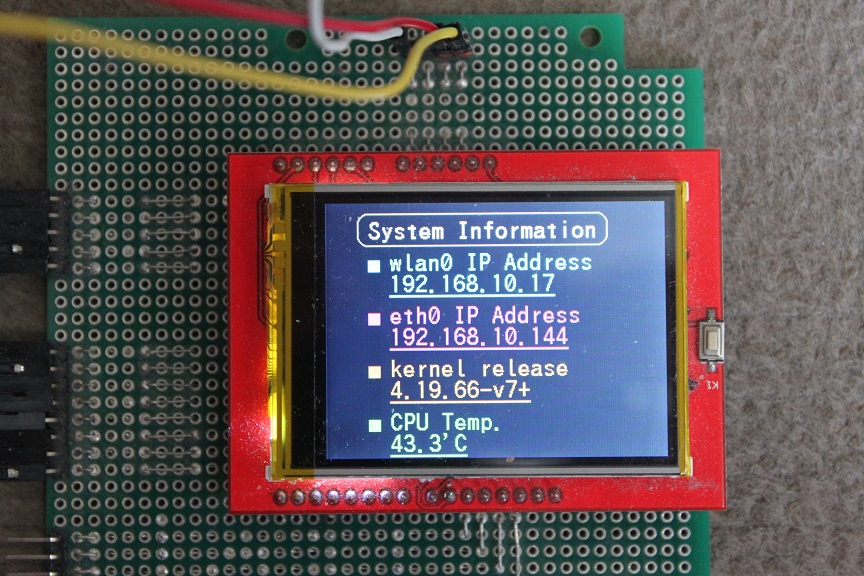
To use this, you need python3 and Pillow.
And reduce the security level of OpenSSL encryption.
$ sudo apt install libtiff5 libopenjp2-7
$ python -m pip install -U Pillow
$ sudo cp /usr/lib/ssl/openssl.cnf /usr/lib/ssl/openssl.cnf.old
$ sudo vi /usr/lib/ssl/openssl.cnf
#CipherString = DEFAULT@SECLEVEL=2
CipherString = DEFAULT@SECLEVEL=1
$ bash ./365calendar.sh

Take wallpaper from bing and display
To use this, you need python3 and imagemagick.
$ sudo apt install imagemagick
$ bash ./bing_wallpaper.sh

Wirering for 16Bit Parallel
| TFT |
|
RPI |
| LCD_RST |
– |
Pin#7 |
| LCD_CS |
– |
Pin#3 |
| LCD_RS |
– |
Pin#5 |
| LCD_WR |
– |
Pin#26 |
| LCD_RD |
– |
Pin#28 |
| LCD_D0 |
– |
Pin#29 |
| LCD_D1 |
– |
Pin#31 |
| LCD_D2 |
– |
Pin#33 |
| LCD_D3 |
– |
Pin#35 |
| LCD_D4 |
– |
Pin#37 |
| LCD_D5 |
– |
Pin#32 |
| LCD_D6 |
– |
Pin#36 |
| LCD_D7 |
– |
Pin#38 |
| LCD_D8 |
– |
Pin#13 |
| LCD_D9 |
– |
Pin#15 |
| LCD_D10 |
– |
Pin#16 |
| LCD_D11 |
– |
Pin#18 |
| LCD_D12 |
– |
Pin#8 |
| LCD_D13 |
– |
Pin#10 |
| LCD_D14 |
– |
Pin#40 |
| LCD_D15 |
– |
Pin#27 |
| 5V |
– |
5V(*) |
| 3.3V |
– |
3.3V(*) |
| GND |
– |
GND |
*When a regulator(It’s often AMS1117) is mounted on the back, it’s operated 5V.
*When a regulator is NOT mounted on the back, it’s operated 3.3V.
NOTE
You can change any pin.
Pin define is “pin.conf”.
Build
cc -o demo demo.c fontx.c tft_lib.c driver/*.c -lwiringPi -lm -lpthread -DILI9341 -DP16BIT
cc -o draw draw.c fontx.c tft_lib.c driver/*.c -lwiringPi -lm -lpthread -DILI9341 -DP16BIT
Start Auto Demo
./demo


SPI Touch Sensor
This module has SPI Touch Sensor.
So you can read touch position.
Use raspi-config to enable SPI.
Wirering for SPI-Touch sensor
| TFT |
|
RPI |
| PEN |
– |
Pin#22(**) |
| T_CS |
– |
Pin#24(**) |
| MOSI |
– |
Pin#19(***) |
| MISO |
– |
Pin#21(***) |
| CLK |
– |
Pin#23(***) |
**It’s defined in the source code.
#define SPI_CHANNEL 0 // /dev/spidev0.0
//#define SPI_CHANNEL 1 // /dev/spidev0.1
#define GPIO_PEN 6
***Can’t change
cc -o xpt xpt.c xpt2046.c -lwiringPi -lm -lpthread
sudo ./xpt

And you can operate Pi using touch sensor.
cc -o touch touch.c fontx.c tft_lib.c driver/ili9341.c xpt2046.c -lwiringPi -lm -lpthread -DILI9341 -DP16BIT
sudo ./touch

4-wire resistive touch screen
OPEN SMART products have 4-wire resistive touch screen, but Pi cannot use this because Pi cannot input analog.
JPEG Decoder
This project uses this JPEG library.
This can reduce the image to 1/2 1/4 1/8.
PNG Decoder
I ported the pngle library from here.
This can reduce the image to any size.


评论